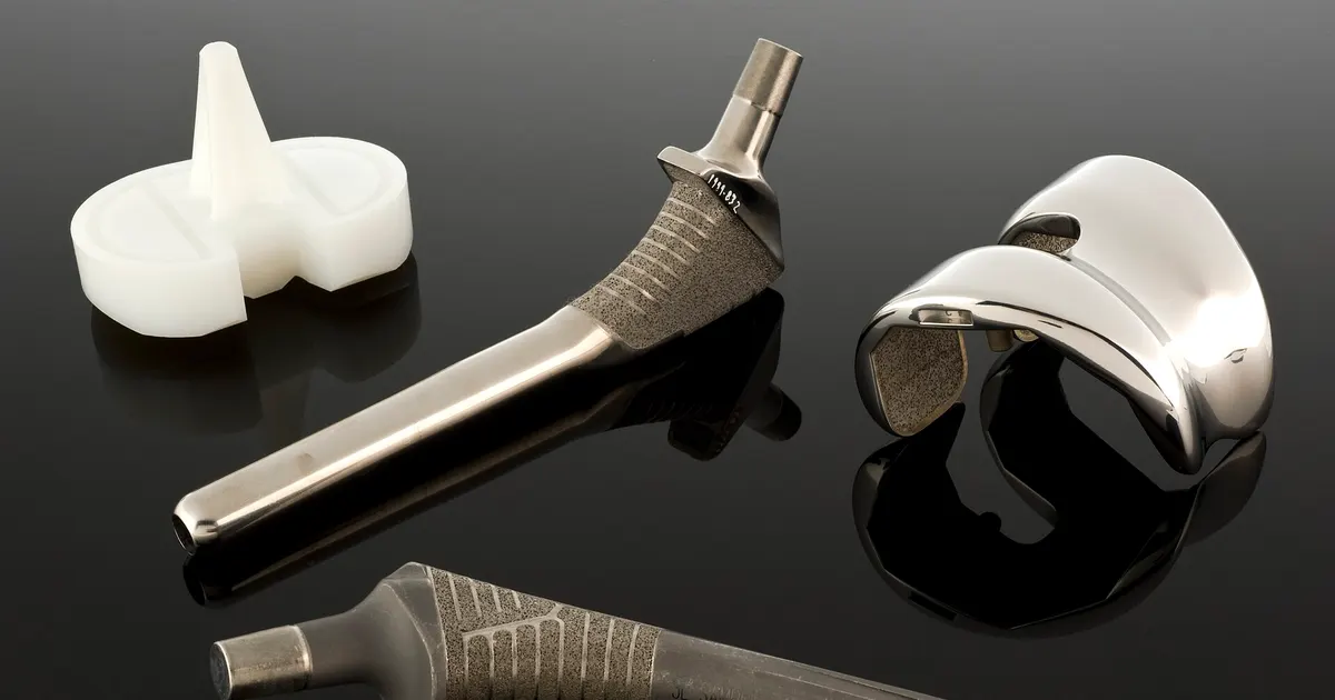
Many orthopedic parts do not look like machined parts. A femoral stem has a tapered, curved body. A tibial trial has a stepped, sculpted top surface. A cutting guide has slots at compound angles. These shapes can be made on a 3-axis mill with many setups, but they are made more consistently on a machine that can tilt and rotate the part, so that the tool reaches each face without moving the part from its datum.
This guide explains when 5-axis machining is the right choice for orthopedic implants and instruments, how it differs from 3+2, what to ask a shop about workholding and probing and how to design a part so that it is easy to cut. The figures are typical values for the partner shops we match RFQs to in southern Vietnam, confirmed per drawing.
Why 5-axis suits orthopedic geometry
A 5-axis machine adds two rotary axes to the three linear axes. The practical benefits for orthopedic work are short and specific.
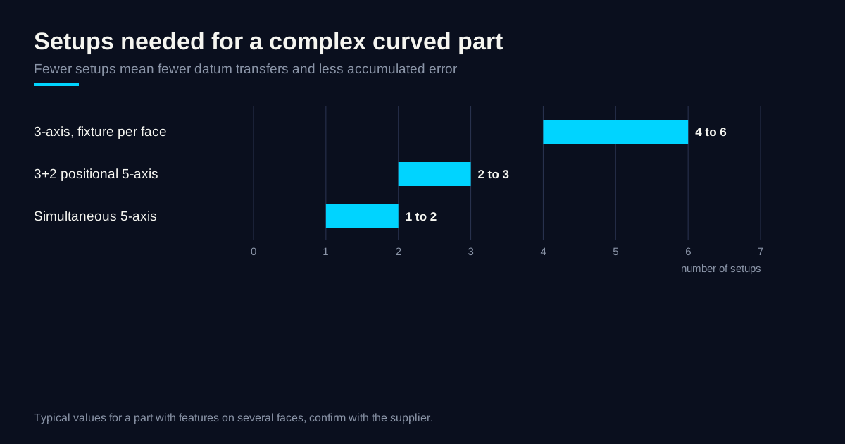
- Fewer setups. Features on five faces can be machined in one clamping. Each setup you remove is a datum transfer that cannot add error.
- Better tool access. Tilting the part lets a short, stiff cutter reach into a pocket or along a curved wall, instead of a long, slender cutter that deflects.
- Better surface on curved faces. Keeping the cutter at a constant angle to the surface gives a more even scallop pattern and less polishing afterwards.
- Fewer fixtures. One universal workholding device can replace a set of dedicated fixtures, which matters for small batches and prototypes.
The cost is a more complex program, a longer verification step and a higher machine hour rate. For a simple part the extra cost is not repaid, which is why the choice is made per drawing.
3+2 versus simultaneous 5-axis
The term 5-axis covers two different ways of cutting.
3+2 machining uses the rotary axes only to position the part. The axes lock and the cut runs on X, Y and Z. It suits prismatic parts with features at several angles, such as instrument bodies, cutting blocks, drill guides and trial components. It is simpler to program, simulate and inspect, and the rigidity is higher because the rotary axes are locked.
Simultaneous 5-axis machining moves all five axes during the cut. It is needed for continuous freeform surfaces, such as the condylar shape of a femoral component, a blended stem transition or a contoured plate. The programs are longer and the verification is stricter, because a small error in the post processor or the tool length can gouge the surface.
For most RFQs, the right first question is which surfaces truly need simultaneous motion. In many parts, only one or two surfaces do, and the rest can be cut as 3+2.
| Part family | Typical route | Why |
|---|---|---|
| Bone screws, pins, pegs | Swiss-type or CNC turning | Rotational parts, long and slender |
| Plates and simple brackets | 3-axis or 3+2 milling | Mostly flat with holes and contours |
| Trial components, sizers | 3+2 or 5-axis | Several faces, sculpted top surface |
| Cutting blocks, drill guides | 3+2 5-axis | Slots and holes at compound angles |
| Femoral stems, necks | Mill-turn or 5-axis | Tapered, curved body |
| Condylar and articulating surfaces | Simultaneous 5-axis, then finishing | Freeform surface, polishing follows |
Workholding decides the result
The machine is only part of the answer. A thin or curved part has to be held without distortion, and the datum has to repeat from part to part.
- Soft jaws and custom nests spread the clamping force and locate the part by its own shape, which helps with curved stems and trials.
- Zero-point systems make the position of the fixture repeatable between machines and between runs.
- Sacrificial tabs or a stub hold the part during the first operation and are removed at the end, which is common for small implants.
- Low clamping force on thin sections prevents the spring-back that shows up as a form error after release.
Ask the shop how the part will be held for each operation, and where the final datum sits relative to the function of the part. A clear answer often reveals the real difficulty before the quote.
Probing and in-process control
Probing on the machine measures the actual position of the part and key features, and corrects the program for it. For orthopedic parts this is useful in three places: finding the work offset on a blank that is not perfectly square, checking a critical diameter between roughing and finishing and confirming the position of a feature that was cut in an earlier setup. It does not replace final inspection on a CMM, but it reduces the number of parts that reach the CMM with a problem.
Tolerances and finish within the capability window
Within the capability window of the partner shops, linear tolerances are typically ±0.01 mm and ±0.005 mm is a best case on selected features, with surface roughness as machined at Ra 1.6 µm typical and Ra 0.8 µm best case. These are confirmed per drawing, never promised in advance. The capabilities page lists the range, and the quality and documentation page lists the inspection records that normally accompany a first article.
For curved articulating surfaces, the requirement is often a form tolerance and a roughness target far below as-machined values, reached by grinding or polishing after machining. These steps belong to the process route and should be written into the RFQ, because they change the machined allowance and the cost.
Designing for 5-axis
A few design choices make a part easier to cut and cheaper to inspect.
- Keep a sensible reach ratio. A cutter that sticks out more than about four to six times its diameter deflects and chatters. Deep narrow pockets raise the cost sharply.
- Use generous internal radii. A larger corner radius lets a larger, stiffer tool do the work. A radius that matches a standard cutter size is cheaper than an odd one.
- Avoid features that need a custom tool. Undercuts, T-slots and special profiles can be cut with form tools, but each one is a purchase and a setup.
- Put the datum where the part can be held. A datum on a surface that is only reachable in a late operation forces extra setups.
- Allow a finishing allowance. If polishing follows, leave a defined allowance on the machined surface and say so.
- State the blank. Bar, forging or casting changes the machining strategy and the traceability record.
Programming and verification
A 5-axis program is only as good as its simulation. Before the first cut, a competent shop simulates the full machine, including the fixture, the holder and the rotary axes, to catch collisions and gouges. For implants and instruments, the first piece is then cut in a softer material, or with a safety offset, and measured before the real blank is loaded. This costs a few hours and saves a titanium blank.
Ask what happens when the design changes. A revision that moves one surface may need a new fixture position and a new probing cycle, and the revision should be tracked so that the first article report refers to the right program version. The program name and revision belong on the traveler, next to the heat number and the drawing revision, so that any part can be traced to the exact way it was made.
Material notes
Titanium alloys such as Ti-6Al-4V cut well with sharp tools, rigid setups and good coolant, but they hold heat at the cutting edge and work harden if the tool rubs. Stainless steels such as 316L and 17-4 PH are tough and gummy, so chip control matters. PEEK is easy on tools but sensitive to heat and clamping force. In every case, the material specification, the form and the certificate requirements should be on the RFQ, and the heat number should be traceable to the finished part.
What the device maker still owns
The partner shops machine to the drawing and to the quality requirements on the purchase order. The device maker owns the design, the design controls, the process validation, biocompatibility, cleaning and sterilization validation and every regulatory submission for its implants and instruments. The sourcing service reviews drawings and matches them to shops, and it makes no claim of regulatory approval for any shop or process.
Checklist before you request a quote
- Which surfaces need simultaneous 5-axis, and which can be cut as 3+2?
- What is the blank: bar, forging or casting, and what is the material specification?
- Where is the main datum, and can the part be held there without distortion?
- Which features have the tightest tolerances, and how will each be measured?
- Is grinding, polishing or another finishing step part of the route?
Send the drawing, the 3D model and these answers through the RFQ form, and a first response with design for manufacturing feedback follows within 24 business hours.