
A drawing tells a shop what the part must be. It does not tell the shop which process steps are most likely to go wrong or which checks protect the buyer. Two documents fill that gap: the process failure mode and effects analysis, usually called PFMEA, and the control plan. Medical buyers ask for them more often on critical parts, and suppliers who have never written one often ask what is expected. This guide explains what each document contains, how they connect, who owns what and what a short, useful version looks like for a machined part.
Formats and approval rules differ between device makers. What follows is a typical structure, not a mandated one, and the buyer’s quality system decides what is required.
What a PFMEA is
A PFMEA examines a manufacturing process one step at a time. For each step, the team asks four questions. How could this step fail? What would the effect be on the part and on the user of the device? What would cause the failure? How would we notice before the part ships?
The answers go into a table with a rating for severity, occurrence and detection. Severity describes how serious the effect is. Occurrence describes how likely the cause is. Detection describes how likely the current controls are to catch the failure before it leaves the shop. In the traditional method the three ratings multiply into a risk priority number, and the highest numbers get attention first. The more recent AIAG and VDA method replaces the multiplication with an action priority table, because two very different risks can produce the same number.
A PFMEA is about the process, not the design. The device maker’s design FMEA and risk management file, which are commonly built around ISO 14971, decide which characteristics are critical to function and safety. The PFMEA asks how the machining process could fail to deliver them.
What a control plan is
A control plan lists the checks that the shop will perform during production. For each process step it normally states:
- the characteristic and its specification, taken from the drawing,
- the measurement method and the gauge,
- the sample size and the frequency,
- the control method, such as in-process probing, a fixture or a poka-yoke,
- the reaction plan if a result is out of tolerance.
The control plan is the place where the findings of the PFMEA become something an operator can follow. It should point back to the PFMEA, so that every high-risk failure mode has a matching control.
How the documents connect
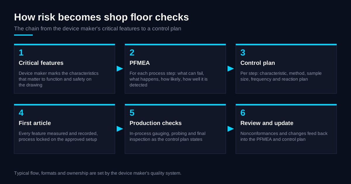
The chain is short. The device maker marks critical characteristics on the drawing or in a quality agreement. The shop writes a PFMEA for the process steps that produce them. The control plan then defines the checks. The first article inspection confirms that the process, run as planned, delivers every characteristic. Production monitoring continues under the control plan, and nonconformances feed back into the PFMEA, so the documents improve with experience.
This chain also shows who owns what. The buyer defines what is critical and what is acceptable. The shop knows its own process, so it drafts the PFMEA and control plan for it. The buyer reviews and approves them, and the approved versions are controlled by revision.
A worked example: a precision bore
The table shows two rows of a PFMEA for one characteristic, a 6.000 mm H7 bore in a stainless instrument body. The ratings are illustrative and shown on a 1 to 10 scale.
| Step | Failure mode | Effect | Cause | S | O | D | Current control |
|---|---|---|---|---|---|---|---|
| Finish bore | Bore undersize | Mating pin does not fit, part scrapped | Reamer wear | 7 | 4 | 3 | Reamer life limit, air gauge check |
| Finish bore | Bore oversize | Loose fit, part scrapped | Wrong tool offset | 7 | 3 | 3 | Probe after tool change, pin gauge |
| Deburr | Burr left at bore exit | Damage to mating part or user | Manual step skipped | 8 | 3 | 5 | Visual check under magnification |
The matching control plan rows for the first failure mode would read as follows.
| Characteristic | Specification | Method | Sample | Frequency | Reaction plan |
|---|---|---|---|---|---|
| Bore diameter | 6.000 mm H7 | Go and no-go pin gauge, air gauge | 1 part | Every 10th part and after each tool change | Stop, segregate parts since last good check, adjust offset, re-verify |
| Bore diameter | 6.000 mm H7 | CMM report | 5 parts | First article and each new lot | Hold lot, notify buyer, root cause |
Notice that the control plan row follows directly from the failure mode. If a failure mode has no matching check, the PFMEA has found a gap.
What a good short version looks like
A PFMEA for a simple machined part does not need hundreds of lines. A useful version for a part with three or four critical features often has 15 to 30 rows. The aim is clarity, not volume.
- List the process steps in order, from material receipt to packing, including outside processes such as passivation or heat treatment.
- Focus on the critical characteristics named by the buyer, and then on a few other features that the shop knows from experience are at risk.
- Write failure modes in plain words, for example bore undersize, thread damaged, wrong material, mixed lot.
- Name real controls, such as a probe cycle, a gauge, a fixture stop or a traveler sign-off, not general statements like operator skill.
- Link every high-risk row to a control plan line.
Where machined medical parts usually fail
A few failure modes show up in almost every machining PFMEA. Tool wear on finishing cuts causes drifting dimensions. Thermal growth causes a part to measure differently after cooling. Workholding distortion on thin walls creates form errors after release. Deburring variation leaves sharp edges on some parts. Material mix-ups, a wrong bar or a wrong heat number in a lot, are rare but severe, which is why traceability controls rate high. Lot mixing at packing is another one. Outside processes add their own failure modes, such as passivation staining or electropolish racking marks, and the shop’s PFMEA should include the steps it subcontracts.
Control plans, sampling and capability data
How many parts to check, and how often, is a decision about risk. A characteristic with a high severity and a history of drift deserves a short interval, for example every tenth part, or a probe cycle on every part. A characteristic that is stable and low risk may need only a first-piece and last-piece check. Where the buyer wants statistical evidence, a capability study such as Cpk on a critical dimension can be added, with the sample size and the acceptance value agreed in advance. This is a separate study, defined by the buyer, and it is not part of a standard first article.
For prototypes, the control plan can be lighter, because the process is not yet frozen. Many device makers accept a simple inspection plan at the prototype stage and ask for the full PFMEA and control plan when the drawing and process are frozen for production. Agreeing that sequence in the RFQ avoids doing the same work twice.
Common mistakes
- Copying a generic PFMEA from another part, with failure modes that do not exist in this process.
- Rating every severity as 10 or every detection as 1, which makes the table useless for ranking.
- Writing controls that no one performs, such as a check that is listed but not recorded.
- Leaving out outside processes, which are often the source of the most severe failures.
- Not updating the document after a nonconformance, so the same failure returns.
- Using a control plan that lists checks but gives no reaction plan.
A short, honest document that the operators actually follow is worth more than a long one that sits in a folder.
Keeping the documents alive
A PFMEA and control plan written once and filed are of little use. They should change in three situations: when a nonconformance or a customer complaint shows a failure that was not on the list, when the process changes, for example a new machine, tool or fixture, and when the drawing revision changes a critical characteristic. Each change should carry a revision number and a date, and the buyer should receive the new version if it affects a characteristic it approved. The quality and documentation page lists the records that normally accompany a first article, and a control plan fits naturally beside them.
What to put in your RFQ
- Which characteristics are critical, and why, so that the shop rates severity correctly.
- Whether you need a PFMEA and control plan, and the format or template you prefer.
- Whether approval is needed before first article, or only before production release.
- The sample size and frequency you expect for critical features.
- Your reaction requirements, such as notification within a defined time after a nonconformance.
The device maker remains responsible for the design risk analysis, process validation and every regulatory submission. The sourcing service reviews drawings and matches them to shops, and it does not claim that any shop holds a certification. When the requirements are written down, send the RFQ and the first response arrives within 24 business hours. The capabilities page describes the inspection equipment available for the controls described above.